In this part I write about the microcontroller I am using and the code. Recently the Raspberry Pi Foundation released a completely new designed microcontroller which can be programmed with MicroPython. Named the RP2040, it is somewhat limited as it does not have Wifi or any other means of wireless communication on board, but it has plenty of ports and is actually even a dual-core controller! So I needed to find a project where I can use it and the Anemometer is a perfect fit.
In fact, the Microcontroller does not have much to do here, its tasks are:
- Count the revolutions of the rotating part
- Report that count every minute
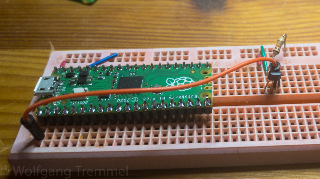
This is really not much. For a sensor I decided to try an Hall sensor (lots of cheap devices use reed relay instead, but a) it has moving parts and b) there is a risk that it bounces and delivers false measurements). If you look at the photo on top you can see the sensor on the right.
So I just wired the sensor to the controller and wrote a (very small) Python program to do the count and reporting:
import time
from machine import Pin

hall = Pin(0,Pin.IN,Pin.PULL_UP)
led = Pin(25,Pin.OUT)

topic = "/Chattenweg5/2OG-Loggia/wind"
prev = 0
count = 0
interval = 60

lastRead = time.time()

while True:
    v = hall.value()
    if v != prev:
        if v == 0:
            count += 1
            led.high()
            # print(count)
        else:
            led.low()
        prev = v
    if (time.time() >= lastRead + interval):
        print(topic,count)
        lastRead = time.time()
        count = 0
I actually just started to learn Python. Weird language if you know C and Perl. But quite capable. The code should be pretty self-explaining, I check if the input value of the sensor has changed, if yes, I do something (count, LED on/off), and every minute I report the count (with maximum about 200 events per minute it is not really worth it doing this multi-threaded.
I glued the sensor into the anemometer, for the controller I included a clip into the print. See below how it looks like.

Next challenge will be to build an anemometer which is powered by wind and transmits wireless via LoRaWAN. Stay tuned.