This is my most complex 3D printed project so far. The idea: I have now quite a number of weather sensors. I measure temperature with solar-powered sensors which transmit their data using LoRaWan at two locations now. I measure if it rains (qualitative measurement only). But I do not measure wind yet. So to keep things simple, I decided on the following parameters:
- Quantitative, but uncalibrated measurement. This gives me “more windy” and “less windy” but not exact values.
- The direction of wind is irrelevant.
- Powered and connected via USB port, wireless might come in another project
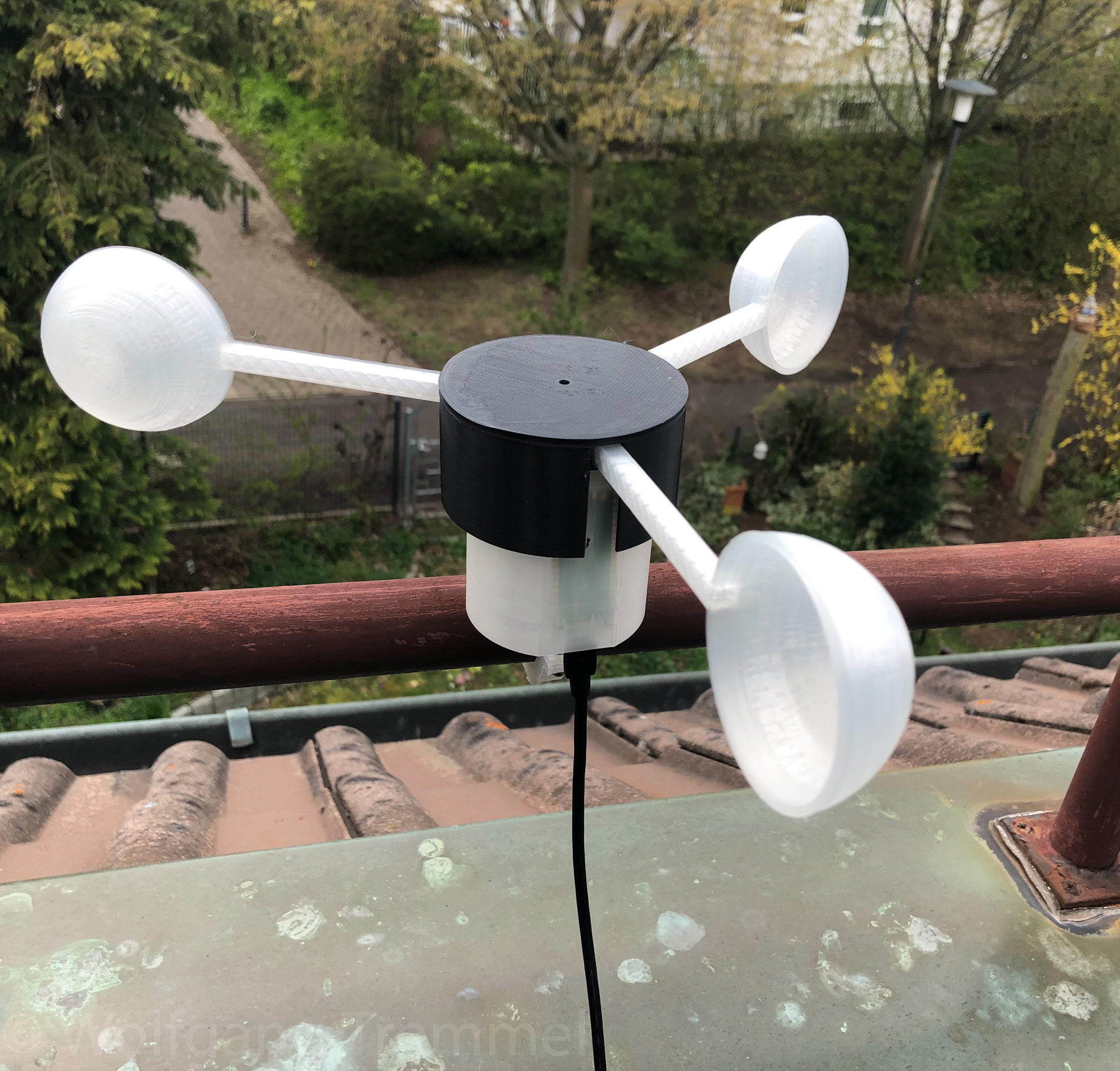
I decided on a “cup” anemometer as I expected this to be easiest to print and it works without being to be rotated into the wind. The cup came first and turned out pretty good. Next was a plate to mount three cups, I had to print this twice, the first one turned out to thick. Also the mount contains of two parts, the upper part is to fix the cups, the lower part contains an axle which goes into a ball bearing in the lower part – this was necessary to reduce friction.
I am not a construction engineer, so it took me some time to figure out how to attach the ball bearing and how to make sure that parts are fastened but still free moving. Two small attachment parts which are simply pressed in did the trick.
Here is my construction in FreeCAD – you can download the files at GitHub and at Thingiverse.

I designed and printed one cup first. It is pretty big – but that means also very low wind will move it. Until now there were no real storms here yet, so no idea how it ill perform at high winds (the maximum I measured so far was 120 rotations per minute).
Next to print was the upper rotational part (the one the cups are attached to). The rotator has two parts because printing overhangs is a pain and holding the two parts together with the same screws that hold the cups is easy. The extra hole in the upper part is for a small magnet.
The lower rotational part has also three holes for the screws and a central axis which goes into the ball bearing (plus a distance holder so the screws keep some distance to the fixed lower part.
The fixed part is quite big as it contains a holder for the microcontroller. I printed a test object just with the ball bearing holder first to see how it fits. I needed something to press the bearing up, for this I used a small part which is just pressed in. Lets see how this holds over time.
Last part was a cover for the top (just fix it with double sided tape) and a cover for the bottom (press it in).
In part two I will write about the microcontroller choice I made and the software.